Entrusted test Process
The entrusted test process begins
The customer expresses their intention to entrust the test to the business department, specifying the product model and test items.
Customer test object delivery
Deliver the test object to the testing center at the agreed time and submit the accompanying technical documentation.
Confirmation of acceptance of test object
Sign the test contract and make a prepayment for the testing fee.
Testing of test object
Carry out various performance tests according to the contract agreement and standard requirements.
Test completed and settlement completed
After the test is completed, the fees will be settled and the customer will pay the final payment.
Delivery Report
Deliver the formal test report to the customer and issue an invoice.
The entrusted test process has ended
Archive test data, complete the entrusted process, and continue to provide technical collaboration services.
Notice for Customers to Handle Entrustment
- 1.Copy of business license, information on value-added tax invoice issuance, and general taxpayer qualification certificate (if general taxpayer qualification certificate cannot be provided, only value-added tax general invoice can be issued)
- 2.Authorization letter for corporate legal representative, declaration (requires signature and official seal of the legal representative)
- 3.The technical conditions, test outline, general assembly drawing, and primary scheme diagram of the test product (the above information must be stamped with an official seal, in one copy, and the electronic version of the technical conditions and test outline should be provided). The technical information should be consistent with the test object and test content, and clear and accurate, including the test object model, name, manufacturer, document number, technical requirements, etc.
- 4.Test entrustment form and configuration form (can be filled out in advance according to the product type, and electronic versions can be carried to handle the entrustment)
Notes
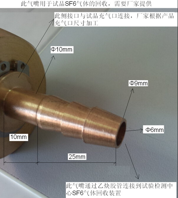
For SF6 ceramic column circuit-breakers, gas insulated metal enclosed switchgear (GIS) and other test object filled with SF6 gas, the testing center provides SF6 gas recovery devices, and the manufacturer needs to provide their own docking gas nozzle. The specific requirements are shown in the figure, click to enlarge and view.
Test drawing requirements
Each manufacture unit shall provide drawings and information in accordance with the requirements of the standard (GB/T11022-2011) when entrusting test object test.
1、Provide the overall assembly drawing. The final assembly drawing must clearly indicate dimensions (length, width, height); The final assembly drawing must clearly indicate the product structure and installation points; The model and name of the main components of the main circuit (such as main switch, disconnector switch, earthing switch, etc.) should be attached on the diagram; The position and model of insulators, bushings, and contact boxes should be indicated on the diagram; The position and model of the transformer should be indicated on the diagram; Products with pressure release devices, provide the location and size of the device.
2、Switchgear requires a circuit diagram (which can be provided separately or attached to the overall assembly drawing).
3、Provide detailed drawings of insulators and bushings, with dimensions indicated on the provided drawings; Provide a cross-sectional view and creepage distance of the insulator.
4、For switches equipped with contact arms for testing, the size and material of the contact arms, the external dimensions of the moving and fixed contacts, and the number of contact fingers should be provided.
5、A cross-sectional view of the arc extinguishing chamber (through the centerline of the main contact and arc contact) is required for SF6 switches.
1、Gas insulated metal enclosed switchgear: The overall assembly drawing must clearly indicate the product structure, installation points, and dimensions, and be accompanied by the model and name of the main circuit components (such as circuit-breakers, disconnector combinations, transformers, busbars, insulators, bushings, operating mechanisms, etc.); Primary circuit diagram is required (which can be provided separately or attached to the overall assembly drawing).
2、 Outdoor isolation (grounding) switch provides a cross-sectional view along the contact axis direction (including the travel of the moving contact); Electrical clearance (including ground distance, contact opening distance, pole spacing); The size of the contact arm, the external dimensions of the dynamic and static contacts, and the number of contact fingers; Schematic diagram of insulation components (post insulators and operating insulators); Schematic diagram of the organization. Detailed drawing of terminals (including dimensions and materials).
3、 Ceramic pillar circuit breaker: schematic diagram of insulation components (pillar insulators); Schematic diagram of the organization.